ok so questions about this have been asked all over the place and i never really saw any definitive answers so i was never able to get my prndl indicator lights working after the swap due to me accidentally cutting the wires without labeling them.... this led me to research how the circuitry worked and ive tested it on my truck to confirm it. i started this thread to hopefully answer everybodys questions and help them get theirs working if they are having problems.
NOTE: i have not actually hooked up the wires to the range switch on the side of the trans yet as i need a few hours to trace them out and do the whole soldering thing. i should have time tuesday to do this and i will report back. but i did manually touch wires where they are supposed to go which did prove it works.
so what i have found is that in the 88-95 (OBS) trucks, the 4 wires that come off the smaller connector on the range switch, which is located on the side of the trans, go STRAIGHT to the instrument cluster. it does not go through the pcm. im not sure about the 96+ trucks with the 411 pcm though. if anybody knows please chime in.
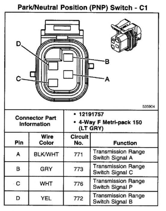
here is the pinout of the 4 pin connector and a chart showing the signal on the wires in any given gear selected.
the way it works is through a series of OPEN/GRND signals depending on the position of the shifter. if you reference above, an example would be if your shifter is in the reverse position... the Blk/Wht and Gry wires would be grounded and the Ylw and Wht wires would remain open (not grounded or 12v+) and this in turn would light up the led under the "R" on your cluster.
I manually grounded these wires with the key in the on position and i was able to get the different indicators lit by grounding different wires as shown in the chart. this would also be a good way to test that your lights and wiring to the cluster are good before shelling out cash for a new range switch. there is an easy way to do this which i will explain next.
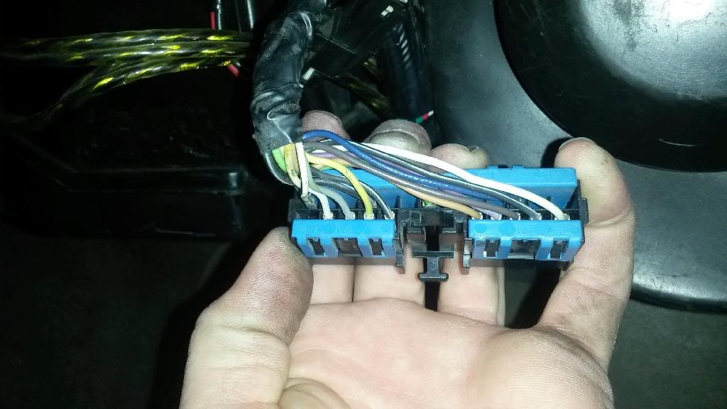
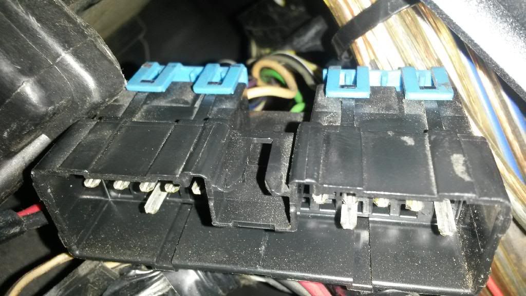
now if your an idiot like me and just cut all the wires without labeling... tracing the wires out is the only option. i was lucky enough to find what i believe is connector C200 that has the 4 wires going to it. it is located behind the glovebox next to the pcm. there was enough slack on mine that i could just pull it down and unclip it for testing without removing the glovebox.
here is what it looks like unclipped. this is the bottom portion with the wires that lead into the engine bay.
here is the upper portion that has the wires that go to the dash.
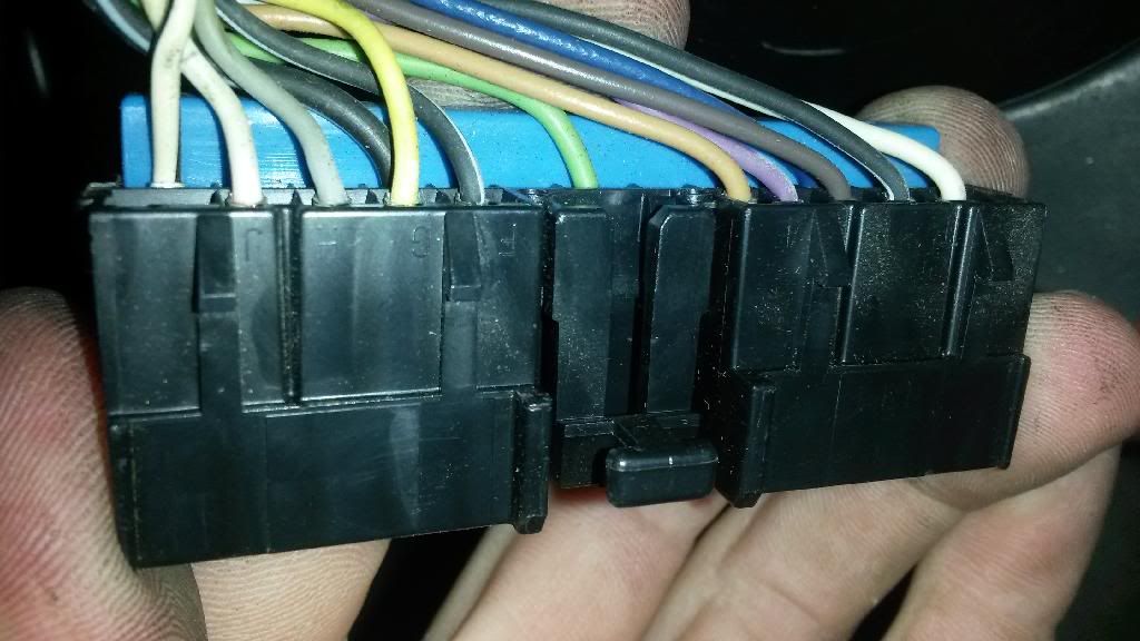
and this one shows which pins my wires are located in.
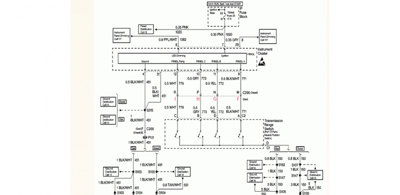
Blk/Wht = Pin F = Signal A
Yellow = pin G = Signal B
Gray = Pin H = Signal C
White = Pin J = Signal P
Just unplug it and find continuity between it and the wires in the engine bay and your ready to splice them into the harness!!!
Here is a diagram i found that i believe was from an astro van. its the best i could find. the numbers on c200 were off by one pin so i changed them to match my plug. your may differ depending on accessories???
that should help anyone find their wires and test the cluster and basically get you going for the obs trucks. ON THE NEWER TRUCKS THOUGH, the signal now goes from the switch to the PCM. the pcm then deciphers it and sends the signal via class 2 serial data to the cluster. thats a whole different ball game but you guys with the newer trucks, i dont think should have this issue anyway.
those of you with 87 and down trucks or anyone doing a custom dash, im not sure how your cluster works but dakota digital sells a PLC deal that will take the signals from the range switch and convert them to a seperate 12v output for each gear. this is useful for custom LED indicators or even powering relays and what not. here is the link for it which is also where i found the chart that explains the signals for each gear.
http://www.dakotadigital.com/pdf/gss-5000.pdf
i hope this helps. if there is anything to add or something i missed, please post.



 Reply With Quote
