so it is.....DONE!
so it is.....DONE!
5.3L '86 Silverado (E/T: 14.37s @ 94mph) - First Time Out!Test-n-Tune (Nov 23, 2008) - 13.65s @ 98mph
I would have done it earlier but since I started the thread I thought it best for someone else to suggest pinning it.I didn't want to seem arrogant to pin my own topic.

See my truck data in the "My Garage" section here... http://www.ls1truck.com/forums/my-ga...tml#post191709
There is a lot of good info here that can answer many questions.
Anyone have a part number and or price on the mid length headers from s&p, I tried to find it on their site but the site is a little unorganized and hard to find stuff on.
Others redheartbeat if youd like to build me a set of those long tubes Id be eternally greatful.
If you can hang tight for a few weeks I'll have the full length header with merge collectors I'm working on completed and will be able to start making them pretty quick. I just don't have a price on them yet.
97 GMC, 2002 LS6.
1991 GMC Syclone #1428
when do we get the wiring harness installation
09 CREWCAB LTZ SILVERADO, 6.2, SIX SPEED, CAI,
Wad up the harness and throw it on top of the engine tonight and turn out the lights. In the morning when you turn the lights back on you will discover that the elves will have integrated your LS1 harness into your existing harness.
See my truck data in the "My Garage" section here... http://www.ls1truck.com/forums/my-ga...tml#post191709
lol damn i cant wait! like christmas all over. maybe i can catch one for a pet
09 CREWCAB LTZ SILVERADO, 6.2, SIX SPEED, CAI,
wow...this thread has given me alot already. I am looking forward to the harness install as well. I have an 03 5.3 that I am installing in a 98 OBS 4.3 truck. so the motor mount thing was a great start.
thanks for the info! keep it coming.
Josh
This is a post from my first conversion that may help you figure out your stock harness should you attempt to use it. It is not 100% accurate so double check everything and if you find something that doesn't jive, be sure to post it here and we'll update it.
1993 OBS Speedometer and Cruise Control wiring
I've been running around with no cruise for the longest time so I thought I'd get around to fixing it. The answer was very simple with help from GasGuzzler. Remove the white DRAC box behind the glove box and pitch it in the corner. Cut the light blue wire with black stripe. Cut the red wire with white stripe. Take a butt connector and stick the two wires in one end and crimp. Take the speedometer signal wire from the PCM and crimp it to the other end. Job done.
BTW, the cruise control cable I used is from a 1998 C1500 with a Vortech V8.
Wiring for a 2001 Fbody LS1/4L60e conversion harness
______________________________________
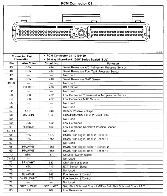
wires removed from the Blue PCM connector....
23 - Low Reference
25 - HO2S Low Signal Bank 2 Sensor 2
28 - HO2S Low Signal Bank 1 Sensor 2
32 - CPP Switch Signal ? what is CPP?
65 - HO2S High Signal Bank 2 Sensor 2
68 - HO2S High Signal Bank 1 Sensor 2
70 - Oil Level Switch Signal
wires removed from the Red PCM Connector....
4 - Air Injection Reaction Solenoid Relay - Coil - Control
13 - Cruise Control Engage Signal
34 - Evaporative Canister Purge Solenoid Control
36 - AIR Pump Relay Control
37 - Cruise Control Inhibit Signal
45 - Evaporative Canister Vent Solenoid Control
53 - Ignition Retard Signal
54 - Fuel Level Sensor Signal
64- Fuel Tank Pressure Sensor Signal
Bundle these wires together from the original Fbody wiring harness and route into the cab of vehicle.....
Blue 33 - Purple - TorqueConverterClutch Brake Switch Signal - to brake switch - normal 12v positive and Zero Volts when brake pedal is depressed .
Blue 46 - Brown/White - Malfunction Indicator Light
Red 17 - Green/White - A/C request switch
Red 30 - Dk Blue - Fuel Enable Control - to VATS if not disabled in the PCM
Red 42 - Tan or Tan/Black - TCC Solenoid Valve Control
Red 50 - Green/White - Vehicle Speed Sensor Signal
These will be your fusible connections to power the engine and fans...
Six fuse power block....
12V - Red - always "ON" from battery
Hook one side of 3 fuses directly to the battery and then make the following connections....
1. 30 amp fuse to terminal 87 on Bosch style relay for low speed fan control
2. 30 amp fuse to terminal 87 for Bosch style relay for high speed fan control
3. 10 amp fuse to PCM Blue 20 and 57
12V - Pink - from ignition "ON" switch to three fused outlets
1. 20 amp fuse to A/C relay terminal 87
2. 15 amp fuse to PCM Connector Blue 19
3. 15 amp fuse to Fuel Pump Relay terminal 87
Bosch Type Relay 1.
Low Speed Fan Relay
Terminal 85 connect to PCM Blue 42 - Dark Green
Terminal 30 Connect to Fan positive
Terminal 86 Connect to constant 12V Power Supply
Terminal 87 Connect to Switched 12V Power Supply
Bosch type Relay 2.
High Speed Fan Relay
Terminal 85 connect to PCM Red 33 - Dark Blue
Terminal 30 Connect to Fan positive
Terminal 86 Connect to constant 12V Power Supply
Terminal 87 Connect to Switched 12V Power Supply
Bosch type Relay 3.
Fuel relay
Terminal 85 connect to PCM Red 9 - Dark Green/White
Terminal 30 Connect to fuel pump 12V input
Terminal 86 Connect to Ground - black/white
Terminal 87 Connect to Switched 12V Power Supply
Borrowed these images from LS1Tech years ago... they might clarify the PCM wiring

Last edited by RedHeartbeat; 05-28-2009 at 11:45 PM.
See my truck data in the "My Garage" section here... http://www.ls1truck.com/forums/my-ga...tml#post191709